2026-10-21 17:17:34
Explore how SANWOOD integrates custom chamber dimensions, BIB racks, sample-inlet monitoring, moisture control and power interlocks into memory burn-in test installations, with representative configurations for SSD and eMMC applications.
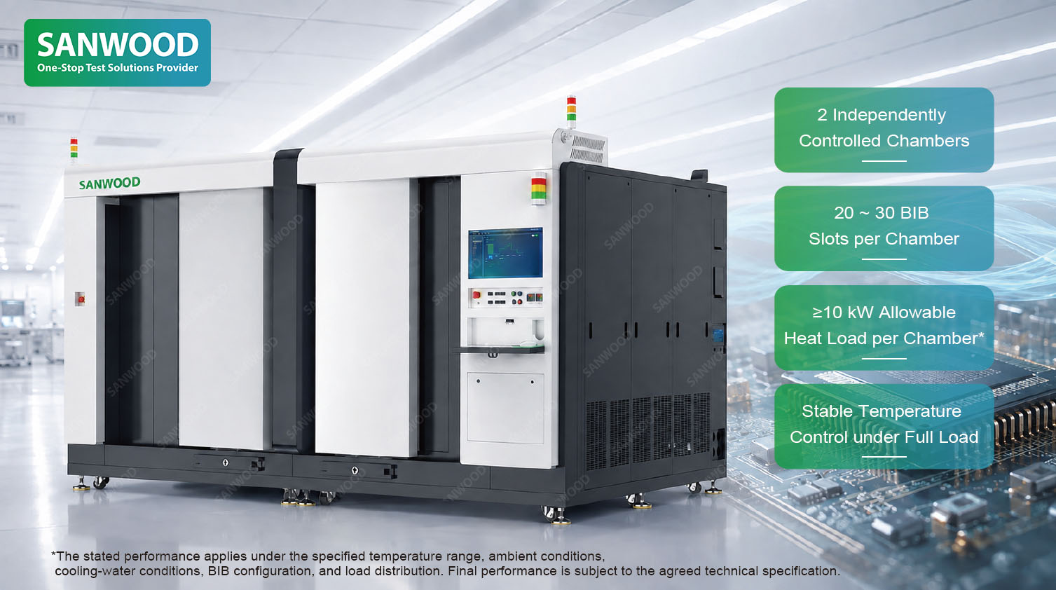
A Memory Burn-in Test System brings together a controlled thermal environment, burn-in boards, and the electrical equipment used to operate and evaluate memory devices. During screening, samples undergo defined thermal and electrical stress to help identify early-life failures before they enter the next production stage.
For manufacturers and test laboratories, integrating these elements has practical consequences. A board needs enough clearance for its connectors. Supporting electronics need suitable cooling. Temperature sensors need to represent conditions around the samples. If the chamber detects a fault, the equipment supplying sample power needs to respond appropriately.
SANWOOD develops Memory Burn-in Test System configurations around these connections. With customizable internal dimensions, BIB rack arrangements, environmental monitoring, and equipment interfaces, the system can be designed to fit the customer's test assembly and operating process.
The burn-in board, or BIB, connects the memory samples to the electrical test resources. Its physical design also shapes the chamber around it.
Board dimensions, socket height, connector position, and cable routing determine how much working space the assembly needs. Layer spacing affects access and the passages available for circulating air. Loading arrangements determine where board guides, rack supports, and door openings should be positioned.
SANWOOD can customize the chamber's internal width, height, and depth according to the customer’s test samples, burn-in board dimensions, and test rack configuration. Sample quantity and operating heat load are considered alongside the mechanical layout.
This flexibility is useful when a customer has already developed a board or established a handling process. A deeper connector assembly can be accommodated in the working-space design. Taller components can be considered when setting rack spacing. Probe locations and cable access can be incorporated before the chamber layout is finalized.
The result is a configuration developed around the populated test assembly, with room for the connections and routine operations that make it usable.
Connect the Test Space with the Electronics Behind It
A memory burn-in installation extends beyond the heated or cooled compartment. Power supplies, driver electronics, interface boards, and connectors all contribute to the operating system.
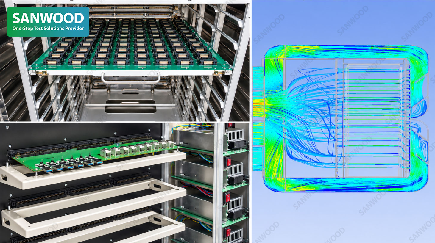
SANWOOD's BIB architecture includes a front test compartment, interface connections, and a rear electronics compartment for power and driver boards. This arrangement allows sample access and electronics access to be considered separately during equipment design.
The thermal environment around supporting electronics also deserves attention. Components used to drive or support the test may require conditions different from those applied to the samples.
For example, the SANWOOD SM-BIB-236D-W uses a BIB assembly mounted on an insulated compartment. Cool, dry air removes heat from the electronics inside that compartment, helping manage overheating and condensation risks.
Electrical installation details support this arrangement. Shielded signal cables are routed separately from high-current power wiring to reduce interference with measurement and control signals. Identified conductors and a modular electrical layout make inspection and maintenance more straightforward.
These features address the day-to-day requirements of a working test station: connecting boards, accessing electronics, maintaining the equipment, and keeping the environmental and electrical functions coordinated.
A temperature setpoint becomes useful when engineers understand where it is measured.
In a populated BIB rack, air passes around sockets, components, connectors, and cables. The temperature at the chamber's supply outlet may differ from the temperature of the air arriving at a particular sample location.
SANWOOD offers a monitoring configuration with 12 repositionable temperature probes. Control feedback can use the supply-air sensor or a probe at the sample air inlet. An offset or direct inlet-temperature feedback can be applied where the selected control strategy requires it.
Movable probes allow the measurement arrangement to follow the test assembly. When the board population or rack layout changes, engineers can position sensors at locations relevant to the revised setup and evaluate the conditions there.
This gives temperature monitoring a practical role in test development and repeatability. It also helps teams distinguish changes in the chamber setting from changes in the environment reaching the samples.
Sample-inlet air temperature, device case temperature, and junction temperature remain different quantities. The test plan determines which reference is needed and how it should be measured.
Memory test programs can include low-temperature operation as well as elevated-temperature exposure. In these applications, moisture management is part of the operating process.
SANWOOD's low-temperature BIB configurations include dry-air dehumidification and humidity monitoring. Dry air helps reduce moisture in the test space, while sensing near the sample air inlet provides information about local conditions.
The documented humidity protection arrangement triggers audible and visual alarms and shuts down the chamber when the configured threshold is exceeded. Multiple sensing locations can be incorporated where localized monitoring is required.
Moisture control also connects the chamber cycle with board handling. A cold assembly exposed to humid room air during unloading may encounter conditions different from those maintained inside the closed chamber. The dry-air supply, temperature transition, and handling condition at door opening therefore need to work together.
Considering this sequence during configuration helps the customer plan how boards move from testing to unloading.
SANWOOD's BIB solutions include different rack capacities, temperature ranges, and chamber arrangements. Three reference configurations illustrate how those requirements can be combined:
| Reference model | BIB arrangement | Temperature range | Listed sample heat load |
|---|---|---|---|
| SM-BIB-236D-W | Four tiers in a single chamber | −50°C to +150°C | 640 W total |
| SM-462D-W | Twelve tiers in a single chamber, with an automatic door | −70°C to +150°C | 3.6 kW total |
| SM2-BIB-777C-W | Twenty tiers per chamber in a dual-chamber system, with automatic doors | −40°C to +150°C | 10 kW per chamber |
The SM-BIB-236D-W is documented for SSD/eMMC applications and includes the insulated electronics compartment. The SM-462D-W and SM2-BIB-777C-W provide additional examples of eMMC test chamber configurations.
These are reference designs. Chamber dimensions, rack layout, sample quantity, and thermal capacity can be developed around the project requirements. Supported heat load at the intended temperature is established for the proposed configuration; the listed temperature range and load do not imply full-load capability at every operating point.
Production capacity also depends on the electrical test resources and the complete batch cycle. Installed board positions provide physical capacity, while the populated boards and test program determine how many samples can operate together.
For a detailed discussion of thermal sizing, see Burn-In Chamber Sizing for BIB Heat Load and Airflow.
During powered testing, the chamber and sample power-control equipment need a defined way to communicate a fault.
SANWOOD's documented power-interlock interface uses a potential-free dry contact. The contact closes on a chamber alarm or fault, signalling the customer's power-control system, which can then disconnect power to the samples.
This connection allows the chamber's protection functions to participate in the response of the overall test installation. Commissioning should verify the complete sequence, from the chamber alarm through the receiving circuit to the intended power action.
Other available protection functions include controller temperature limits, an independent over-temperature protector, temperature-deviation protection, and circulation-fan motor monitoring. Smoke detection is described for the rear power-module compartment and electrical control cabinet.
The project configuration determines which protections are required and how the connected equipment responds.
Loading and unloading recur throughout the equipment's working life. Their requirements deserve attention while the chamber and rack are being designed.
SANWOOD's automatic-door configurations provide a basis for integration with a defined production handling process. The documented safety arrangement uses a light curtain to monitor the door travel area. Entry into the detection zone raises an alarm and inhibits door movement.
For installations involving automated loading, the rack position, board guides, door opening, handling mechanism, and control handshake need to align. Maintenance access should remain part of the same layout so that operators and service personnel can inspect boards, reach connectors, and work on the equipment.
Planning these details together helps the system fit the production space and the way the customer intends to use it.
The complete Memory Burn-in Test System must support the intended device operation and evaluation.
Environmental control, electrical stress, functional checks, and result analysis each contribute to that process. The specified test electronics and software determine the supported memory interfaces, operating patterns, response comparisons, and reporting functions.
Where integrated burn-in and core testing are required, these functions should be identified in the project scope together with the simultaneous test capacity and required test coverage.
This is particularly relevant when moving between memory architectures. DRAM, raw NAND, and managed eMMC require different electrical operations and result interpretation. SANWOOD's memory burn-in testing guide explains those device-specific considerations.
Defining the electrical scope alongside the chamber design gives both teams a shared basis for interfaces, operating loads, monitoring, and equipment acceptance.
Founded in 1995, SANWOOD manufactures environmental test chambers, temperature forcing systems, and memory burn-in systems. The company operates an approximately 30,000 m² manufacturing facility in Dongguan, China, and serves customers in more than 100 countries and regions.
SANWOOD provides worldwide installation, maintenance, and repair support, together with remote technical assistance, operator training, preventive maintenance, and equipment upgrades.
For an international installation, equipment configuration and service planning can develop together. Site utilities, commissioning responsibilities, training, spare parts, and maintenance access all influence how smoothly the system enters operation and remains supported.
Your populated board drawing is a useful starting point.
Share the sample dimensions, BIB size, test rack arrangement, target batch quantity, temperature profile, and operating heat load. Information about the electrical test equipment and loading process will help define the interfaces and supporting functions.
Contact SANWOOD to discuss a Memory Burn-in Test System with internal dimensions tailored to your samples, burn-in boards, and test racks, supported by the environmental controls and service arrangements your application requires.
Sanwood is not just a company; it is a commitment to delivering high-quality products that stand the test of time.

 English
 中 文


 info@sanwood.com