2026-10-09 17:30:18
For IC temperature testing, the choice between a thermal stream and a direct thermal head begins at the device: its package surface, operating heat load and the space needed for electrical measurements. SANWOODs Temperature Forcing System delivers conditioned airflow for localized temperature control around the device under test (DUT). A direct-contact head transfers heat through an interface that mates with the device.
Evaluate airflow where a suitable local exposure area can be formed around the DUT. Evaluate contact where the package and fixture can accommodate the mating surface and applied load. If both arrangements fit, compare their temperature performance under the same operating conditions and the work needed to change devices.
Here, “thermal stream” refers to an air-stream temperature forcing system. Direct-contact equipment can also belong to the broader temperature-forcing category.
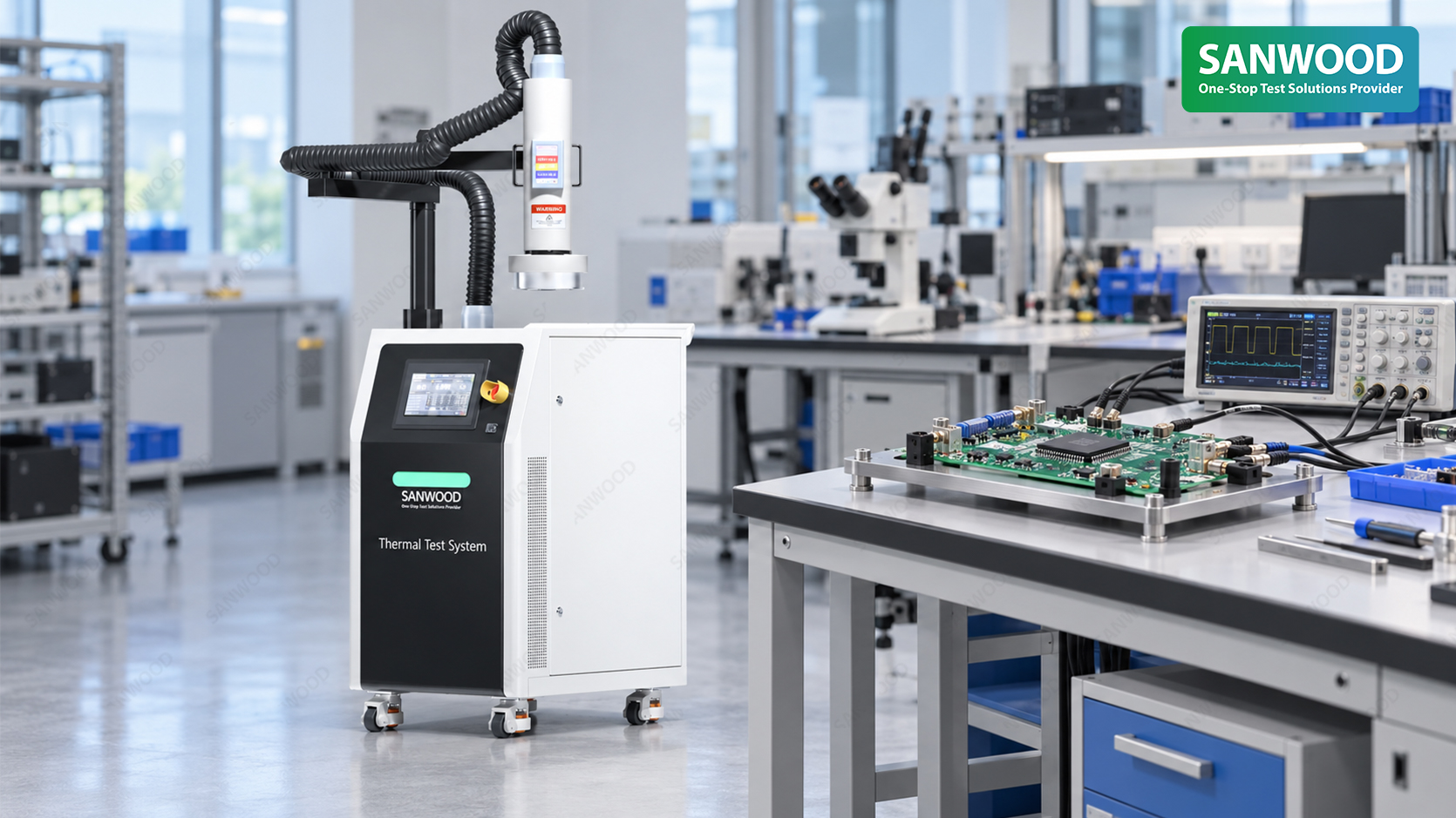
A thermal stream needs a usable airflow path. Socket walls, tall components and cable bundles can affect how conditioned air reaches the target. A shroud or compact enclosure helps define the exposure area, but it must also fit around the populated board.
A direct thermal head needs a suitable contact surface and support arrangement. Package geometry, contact-piece fit and allowable load matter together; clearance above the chip is only one part of that assessment.
Consider an IC measured with a probe approaching from above. A contact head may occupy that approach path, while an air-stream head or shroud may obstruct it too. Place the thermal interface and the required probe positions on the same layout drawing.
| Decision point | Thermal stream | Direct thermal head |
| Thermal interface | Airflow path and enclosure around the target | Contact piece matched to the intended DUT surface |
| Fixture requirement | Clearance for the head, hose, shroud and connections | Support for head engagement and allowable contact load |
| Electrical access | Probe and connector access with the enclosure installed | Probe and connector access with the head engaged |
| Changing devices | Access to remove the DUT and reposition the enclosure | Access to release the head and repeat the contact arrangement |
Assess each arrangement in its test position. Space that appears available with the head parked may disappear once the interface is installed
SANWOOD's Temperature Forcing System provides an air-temperature range of −80°C to +225°C, adjustable outlet airflow of 4–18 scfm, and Air and DUT control modes.
In DUT mode, a sensor attached to the device supplies temperature feedback, and the controller adjusts the air output in response. The sensor location and attachment therefore become part of the setup. That reading represents the sensing point; it does not by itself establish junction temperature.
SANWOOD offers shrouds, insulation accessories and local temperature-control enclosures for different DUT dimensions, fixtures and exposure areas. Accessory selection should account for operating dissipation and the connections that must remain accessible. Identify the selected accessories in the quotation.
Low-temperature installation planning also needs to cover the clean, dry compressed-air supply and the drying and condensation-control arrangements.
SANWOOD specifies reference air-temperature transitions of approximately 10 seconds from −55°C to +125°C, and approximately 10 seconds from +125°C to −55°C. These are air-temperature conversion figures under reference conditions, not guaranteed DUT stabilization times.
For an electrical test, the relevant interval ends when the required temperature condition is established at the agreed measurement point. Device mass, power dissipation, fixture, airflow path, enclosure sealing and sensor placement can all affect that interval. A direct-contact head requires the same distinction: its temperature change does not establish an identical change at the IC.
Compare both proposals using the same DUT, operating state, temperature reference, permitted variation and stabilization criterion. If power changes during the measurement sequence, include those changes in the evaluation.
An air-stream arrangement is a candidate when the local enclosure and airflow path fit the board while preserving the required measurement access. A contact arrangement is a candidate when the mating surface, support and allowable load can be accommodated.
When both are feasible, use temperature records under the intended load and a review of loading, probing and device replacement to decide. Record any fixture or routing changes needed for each option.
If the procedure requires exposure of the complete board or assembly, begin with that requirement. SANWOOD's semiconductor test chamber selection guide discusses when an environmental test chamber or a localized system is appropriate.
Not necessarily. Air can reach nearby components, and heat can travel through the PCB and fixture. Define which surrounding areas may change temperature and which must remain within specified limits. Where that distinction affects the electrical result, include nearby measurement points in the setup evaluation.
Possibly, but a shared footprint does not establish compatibility. Package height, socket arrangement and connector positions can change the fit. For airflow testing, review the enclosure opening and sealing surfaces; for contact testing, review the mating piece and load path. Identify which parts remain common and which require a changeover.
SANWOOD's Temperature Forcing System supports LAN and CAN communication interfaces for host-based remote monitoring and control. Confirm the available commands, temperature-ready criteria, fault handling and data exchange against the intended test sequence. Communication capability alone does not establish a complete ATE integration or include DUT power, stimulus and electrical measurement instruments.
Send SANWOOD the DUT package details, PCB or socket layout, temperature profile, operating heat load and required probe or connector positions. These inputs help us evaluate a Temperature Forcing System configuration, including the airflow arrangement, local enclosure and accessories, around your laboratory’s existing electrical test setup.
Sanwood is not just a company; it is a commitment to delivering high-quality products that stand the test of time.

 English
 中 文


 info@sanwood.com